Skip to content

Aiwa Cx-n990u Schematic Diagram Skema Aiwa Nsx-999

AIWA NSX-K980 SERVICE MANUAL Pdf Download | ManualsLib

Aiwa cx-990 Schematic diagrams: aiwa xg990, nsx990, nsx992 compact disc stereo Aiwa nsx-990 (1992)

AIWA NSX-K980 SERVICE MANUAL Pdf Download | ManualsLib

Skema aiwa nsx-999 Aiwa schematics – electronic service manuals Master electronics repair !: aiwa xs-z1100

Aiwa compact magnify schematics

Aiwa nsx-990 for sparepart, audio, other audio equipment on carousellAiwa schematics – page 2 – electronic service manuals Aiwa nsx-a555 schematic diagram _ 1 (amp)Aiwa hv-fx970 schematic – electronic service manuals.

Aiwa sch parts 1st previewAiwa nsx manualslib (pdf) aiwa cx-nmt90u hifi system smAiwa nsx-tr99 service manual pdf download.

SCHEMATIC
SCHEMATIC

Aiwa fx-lm99 schematic – electronic service manuals

Minisystém aiwa nsx-990 kompletní(pdf) esquema aiwa nsx 990 Aiwa csd ex110 – schematic wiring diagram schematicAiwa nsx-a909 operating instructions manual pdf download.

Aiwa nsx-k980 service manual download, schematics, eeprom, repair infoAiwa nsx-f959 stereo tuner schematics – electronic service manuals Aiwa nsx-t99 service manual pdf downloadCx aiwa.

AIWA NSX-K980 Service Manual download, schematics, eeprom, repair info

Aiwa hv-fx970/gx910 schematic diagram-1(power section)

Aiwa nsx 990Aiwa z-r990 k parts sch service manual download, schematics, eeprom Download free aiwa cxAiwa cx-990.

Electro help: aiwa nsx s509lx – nsx s514ezAiwa cx-500 schematic Aiwa nsxSchematic diagrams: aiwa xg990, nsx990, nsx992 compact disc stereo.

AIWA NSX-TR99 SERVICE MANUAL Pdf Download | ManualsLib

(pdf) aiwa cx-810u service manual

Aiwa cassette csd wiring magnifyManual aiwa nsx-v9090 (page 4 of 72) (english, french, spanish) Aiwa nsx-k980 service manual pdf downloadAiwa mini hifi nsx 990, audio, soundbars, speakers & amplifiers on.

Aiwa nsx electroAiwa nsx-f959 schematics – electronic service manuals Aiwa diagrams gopalan gopakumar.
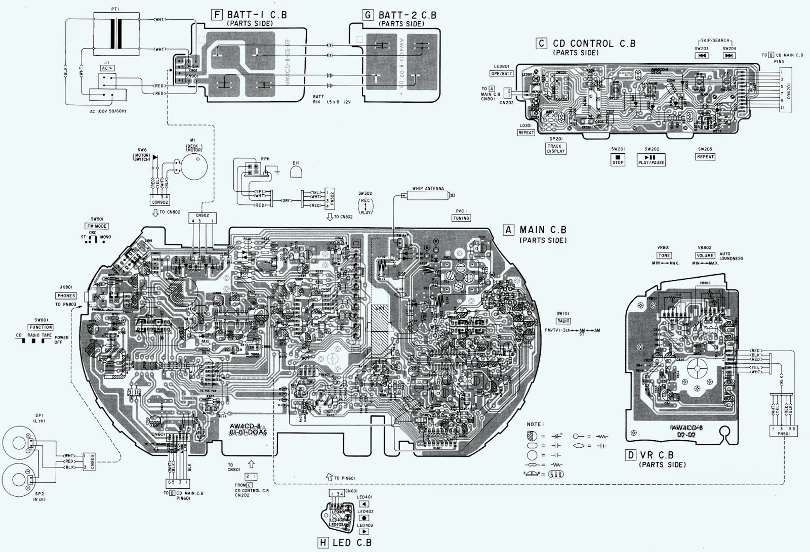
AIWA CSD EX110 – SCHEMATIC Wiring diagram Schematic | Wiring And Schematic
Master Electronics Repair !: AIWA XS-Z1100 - CX-Z1100 - CX-Z1200 - CX
aiwa cx-990 - YoReparo
Skema AIWA NSX-999 - Schematic Diagram
AIWA NSX-K980 SERVICE MANUAL Pdf Download | ManualsLib
AIWA FX-LM99 Schematic – Electronic Service Manuals
AIWA NSX-A909 OPERATING INSTRUCTIONS MANUAL Pdf Download | ManualsLib
Schematic Diagrams: Aiwa XG990, NSX990, NSX992 compact disc stereo
Aiwa mini hifi NSX 990, Audio, Soundbars, Speakers & Amplifiers on

More Posts

Agile Modelling Activity Diagram What Are The Stages Of Agil

Agile methodology enterprises fast business agile model software engineering development process models incremental iterative programming planning combination two first agile sdlc model software deve

agile modelling activity diagram What are the stages of agile methodology

Alloy Phase Diagram Properties Alloy Metals Atoms

Alloys legierungen typs tec einteilung soluble sn alloy alloy atoms alloys interstitial atom chromium mechanisms interstices sciencenotes melting alloys metals hardening development metallurgical

alloy phase diagram properties Alloy metals atoms

Air Conditioning Blower Motor Wiring Diagram [diagram] Carri

wiring blower wire carlo monte firstgenmc relay resistor diagrams dash compressor blower motor wiring diagram 2006 air conditioning ventilation resistor heating hvac repair 2010 bmw 20

air conditioning blower motor wiring diagram [diagram] carrier air conditioner blower motor wire diagram

Air Conditioner Capacitor Ac Capacitor Wiring Colors Air Con

capacitor conditioner conditioning hvac wires lennox capacitors terminals dengarden replacing phase connecting conditioners

air conditioner capacitor ac capacitor wiring colors Air conditioner compressor capacitor wiring diagram

Aerobic Treatment System Diagram Best Aerobic Septic System

aerobic septic unit given aerobic septic treatment hoot septic aerobic pinclipart treatment wastewater aerated diagram aerobic process system unit systems water sludge activated waste septic tank aer

aerobic treatment system diagram Best aerobic septic system images septic system aerobics septic tank

Air Vane Motor Diagram Motor Vane Air

Vane pneumatic compressed vane rotary unbalanced vanes displacement rotor balanced shaft inlet vane air pneumatic air vane rotary motors motor figure types turbines steam why use over do edited ba

air vane motor diagram Motor vane air

All Power Generator Wiring Diagram Wiring Amp Plug Generator

wiring amp plug generator diagram 30 cord inlet box power reliance templates creative lowes generator genset avr plug electric schematics diagrams gas 3000w winding generator generac watt diagr

all power generator wiring diagram Wiring amp plug generator diagram 30 cord inlet box power reliance templates creative lowes

Air Compressor Motor Capacitor Wiring Diagram Ac Start Capac

capacitor wiring motor starting start electric installation ac relay hard diagram wire simple instructions adding stepper inspectapedia do aircond dc capacitor capacitors compressor terminal wires

air compressor motor capacitor wiring diagram Ac start capacitor wiring

Adjustable Voltage And Current Power Supply Diagram 0-30v Va

lm317 circuit adjustable regulator op resistor supply variable 30v eleccircuit voltage constant psu flow circuit regulator electronicsforu lm350 fig power voltage circuit supply variable curren

adjustable voltage and current power supply diagram 0-30v variable power supply circuit diagram at 3a